
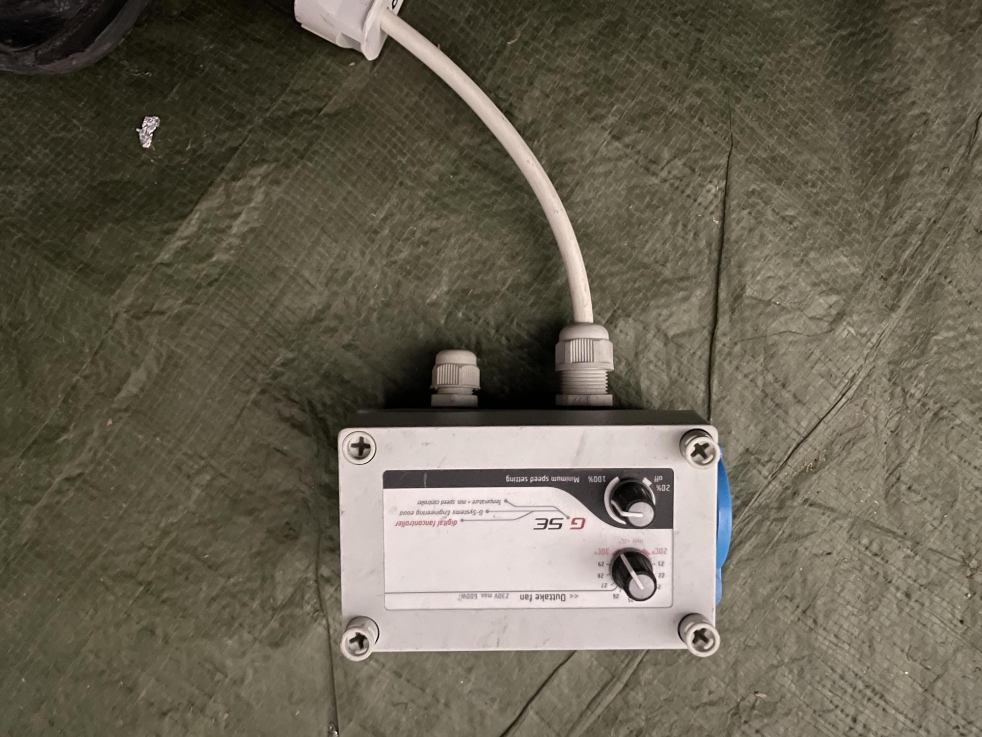
GSE Steuerung zu retten?

HanzUndFranzstarted grow question 5mo ago
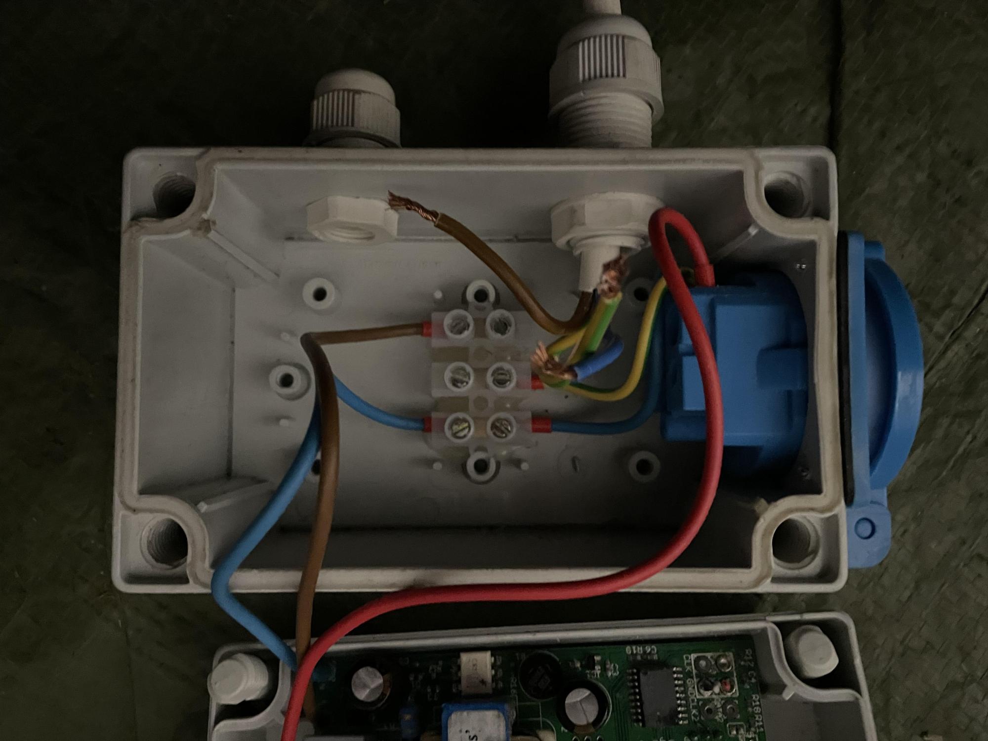
defekte GSE lüftersteuerung. Nich clever genug zum anschließen, oder wirklich ohne Funktion, wegen vllt des fehlenden Temp Sensor? L,N& PE waren links (rechts auf den Bildern#steht auf dem Kopf) mit unter die listerklemme geklemmt. War das richtig?
Solved
likes

Caertneranswered grow question 4mo ago
Links oben Temperatursensor (fehlt - analoges System - geht fest auf min. Drehzahl)
Rechts oben Stromanschluss (nicht angeschlossen - Farben entsprechend in die Klemme)
Rechts blaue Steckdose (Lüfter einstöpseln).
Wenn du mit der eingeschränkten Funktion leben kannst (hab selber auch nix anderes). Schließ an und teste.
Eigentlich sollten nur digitale System in einen max. Drehzahl - Notlauf gehen.

PurpleHazeSoldiersanswered grow question 5mo ago
Hello electrician from the Netherlands here, the brown wire (L) and the blue wire (N) are your power supply. You need to connect the brown with brown and the blue with blue only. The green and yellow wire (PE) is your safety and you can only connect them with eachother.
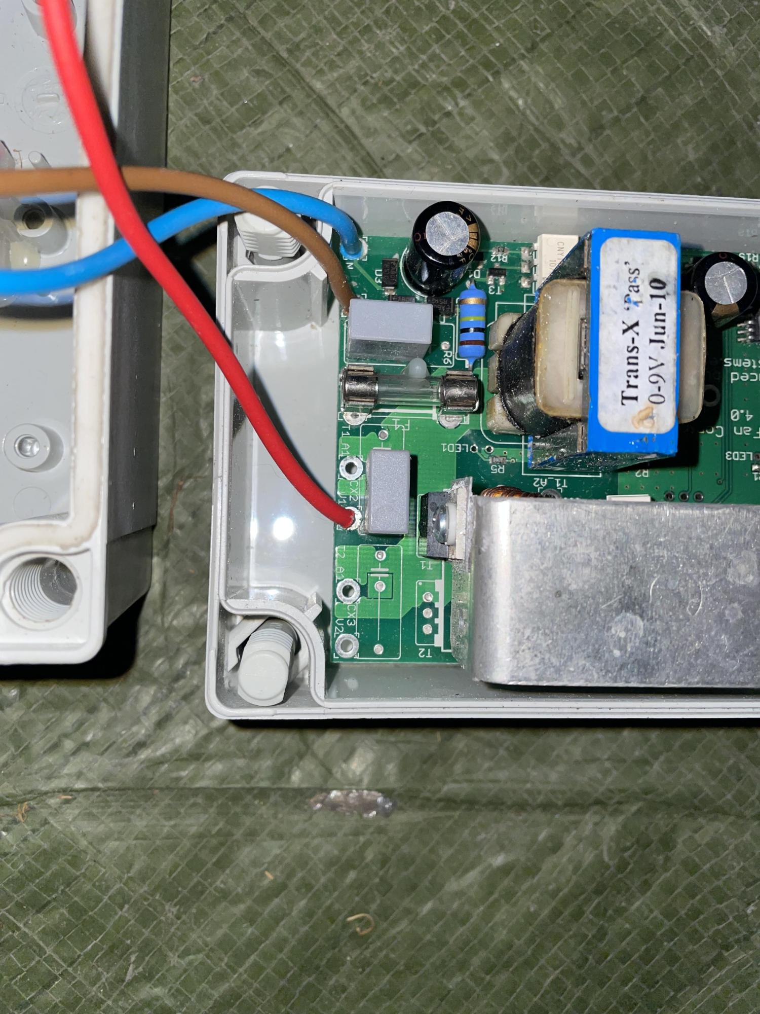
The red wire comes from your controller. You can control the fan speed with the buttons and the controller cuts off the power supply input and only gives the desired output that you set with your buttons and this desired power goes throug the red wire to your output so to your fan connected to this output.
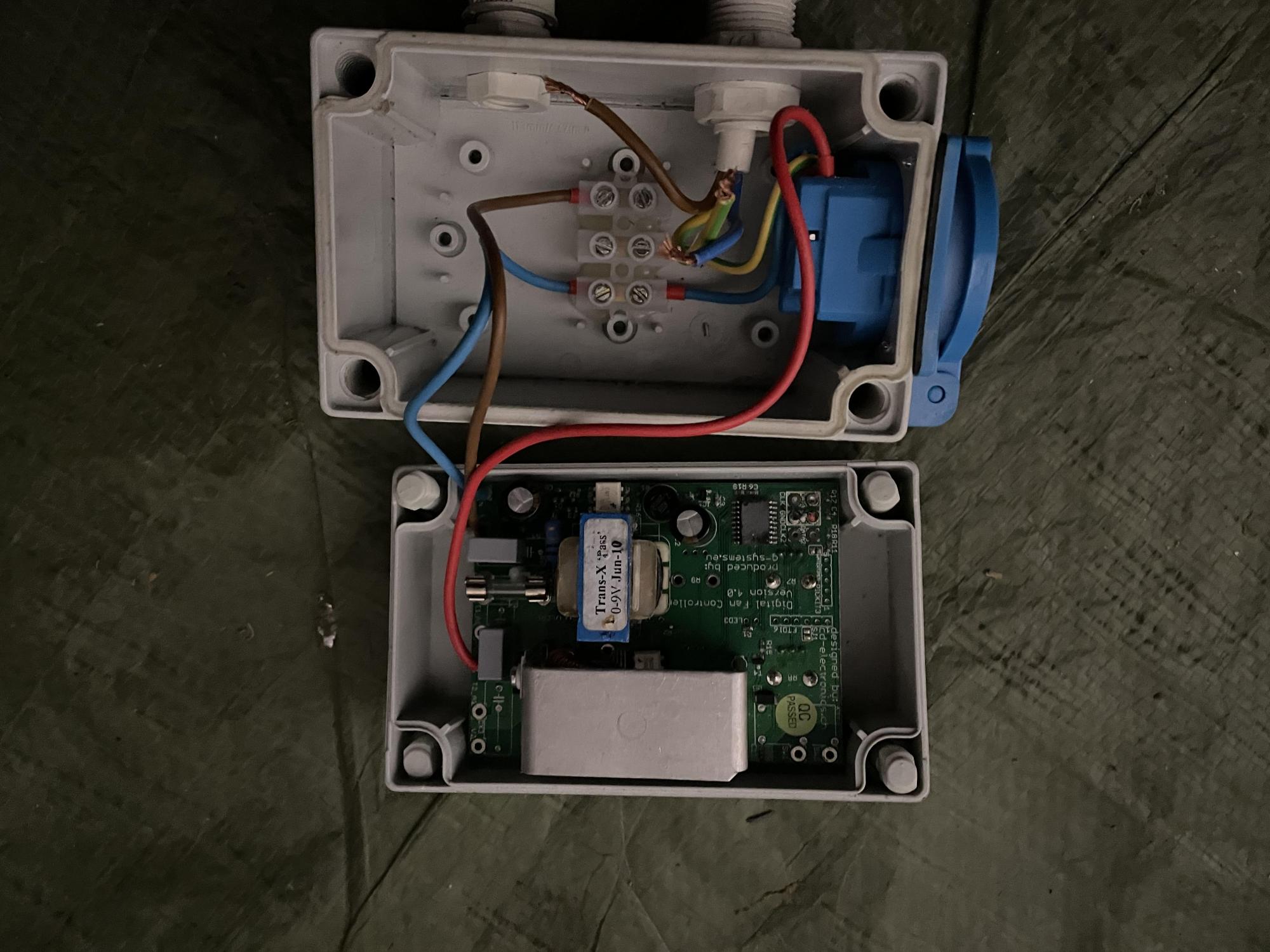
When you connect it like this it should work without a sensor with the minimum speed setting button (this button is made to let it work without sensor) except when one of the components is broken that means that the controller is broken and need to be replaced.
1 like
Complain

Crop_Topanswered grow question 5mo ago
The control board appears to use brown + blue for supply, and the red wire likely looks like the switched output/live to the blue socket.
So, to answer your question:
No, PE should not be treated like L or N on the control board side.
Normally for a unit like this:
• L (live) goes to the controller input
• N (neutral) goes to the controller input
• PE (earth) does not go to the PCB as a functional conductor unless the board specifically has an earth terminal
• PE should be joined through from supply cable to the output/socket earth terminal
Based on your pictures, the terminal block seems to be acting as a junction point:
• one side for incoming mains
• one side for the socket/output
• then the PCB takes L/N, and returns a switched live on the red wire
That part is plausible.
What is not okay is the current state of the exposed conductors and uncertain earth routing.
About the missing temperature sensor:
• Yes, if this is a GSE fan controller that depends on an external temp sensor, then without the sensor it may not regulate correctly
• Depending on the model, it may:
• do nothing,
• run the fan at minimum,
• run full speed,
• or behave erratically
So the missing sensor could absolutely make it seem “without function,” but it does not explain unsafe-looking wiring.
My honest take from the photos:
• It may not be defective
• but it is not safely wired right now
• and without the sensor, it may also be incomplete / impossible to test properly
If this still doesn’t help you out I would highly recommend posting on a local electricians page on Facebook. That would be your best bet and probably have your question answered quickly. Best of luck!
likes
Complain

Ultravioletanswered grow question 5mo ago
Ye electrical codes are regional rather than international, wire colors can indicate entirely different functions depending on the country, leading to boo boo.
likes
Complain


Organomananswered grow question 5mo ago
You are asking random potheads about electrical work that if done incorrectly could burn your home to the ground???
Just buy a new unit!
1 like
Complain